JARDUM.core Manual
Table of Contents:
Table of Contents:IntroductionCare and MaintenanceUser InterfaceStatus BarEngine Data PageCamera PageSwitches PageStereo PagePlaying the RadioDynamic Source ButtonZone ControlStoring FavoritesPlayback using an External SourcePlayback using USBUSB Browse MenuPlayback using BluetoothMusic QueueMap PageMap InterfaceWaypoint ManagerTrack ManagerMap OptionsWake PageAdjusting Ballast LevelsAdjusting Tab LevelsRider ProfilesZero Off GPS Cruise ControlRemotesEncoder (aka Smart Knob or VDC)ICE RemotesSettings MenuGeneral SettingsUnitsLanguageTime and DateUse GPS TimeTime ZoneDaylight SavingsSoftware Version and System UpgradeReboot to LoaderSettings Import/ExportImporting SettingsExporting SettingsRestore Factory SettingsFactory ResetDebugRestricted SettingsDisplay SettingsAdjusting the BacklightGPS / Ambient Auto-BrightnessThemeTheme ColorTheme Secondary ColorStereo PageMap PageUse WakeUse MarineUse Full-Page SwitchesHorizontal Encoder OrientationCustomizing the Startup ScreenBluetooth SettingsPairing a Bluetooth AccessoryUnpairing a Bluetooth AccessoryMap SettingsSatellite StatusShow TracksShow WaypointsMap ColorImporting or Exporting Tracks and WaypointsImporting Tracks and WaypointsExporting Tracks and WaypointsPower Distribution Module SettingsConfiguring PDMsOutput TypesMarine Specific OutputsAudio SettingsTuner RegionAmplifier OutputsName ZonesEngine (Vessel) SettingsPresetsCAN Bit RatesCAN TerminationFuel Sender LocationFuel Sender CalibrationConfigure GaugesCamera PageModifying CamerasCruise ControlsUse MEFI Cruise [BETA]Engine DiagnosticsWake SettingsNumber of Ballast TanksBallast Empty / Fill TimesNumber of TabsActuatorAuto Retract
Introduction
Care and Maintenance
General maintenance is not required: however, It is recommended to use a soft cloth for cleaning the unit. Window cleaner or alcohol can also be used to clean the glass portion of the display. Do not use harsh or abrasive cleaners on the unit.
User Interface
The device interface provides access to all of the features in the device. The features are dependent on the accessories you have connected to the device and may need to be enabled through your dealer. You may not have all of the options and features discussed in this manual.
The pages along the left of the screen provide quick access to the main features of your device. Pages adjust the appearance of the user interface to increase the viewing area of the current page. For example, the stereo displays a view related to the media player features. You can edit the pages you commonly access in settings. Below is a list of pages:
- Engine Data
- Stereo
- Map
- Wake Control
- Switches
Note: Each page re-positions critical gauges and settings to the top and bottom of the screen. Current speed and volume levels move to the top in the status bar, and other engine data move to the bottom bar.

Status Bar

The status bar displays the time, connected Bluetooth device status, stereo, RPM, and speed depending on configuration

No GPS Lock - Check Satellite Status in Menu > Maps > Satellite Status

Check Engine Light - Shown when one or more device transmits an active diagnostic trouble code (DTC). Touch icon to bring up description.
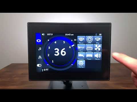
Engine Data Page

This area displays all of the vital engine gauges and system information for the vehicle/vessel in a large, easy to read format. They are as follows:
- RPM
- MPH
- Fuel
- Oil Pressure
- Engine Temperature
- Battery Voltage
Camera Page
Switch between two cameras by tapping the camera page. To return to the main page, tap outside of the camera page.

Switches Page
If the device is equipped with a PDM , the Switches icon appears on this page and allows the operator to controls for both the lights and switches on the vessel/vehicle. Touch each component to turn on or off.


Note: The switches page can also appear on the left column as a full page switch page. Tap there to open the Switch page

Stereo Page

This area always displays the current stereo source and the volume level of the audio system. Tapping the +/- on the volume level increases or decreases the volume. Tapping the volume horn icon mutes or unmutes the audio system.
Playing the Radio
The Music Player contains the following items:
- Currently playing track and artist (or radio station).
- Previous Track/Next Track - skips to the previous song or the next song if using USB input or Bluetooth or it changes the frequency/channel if using AM or FM.
- Play/Pause - toggles Play/Pause if using USB input or Bluetooth.
- Source - displays the currently selected audio source.
- Favorites - toggle a favorite channel on/off.
- If using USB input or Bluetooth, the shuffle and repeat button appears.

Dynamic Source Button
The Dynamic Source button is the first button on the left on the media player tab. The view of this button changes dynamically according to the currently selected audio source. This tab displays different functions according to the selected source. The different possible sources are listed below:
- FM and AM radio
- Weather Band
- USB device
- Bluetooth Audio
Zone Control
The Zone Control page allows the operator to individually adjust the volume level for each of the zones of the vessel/vehicle.

The master volume controls the volume level of all zones, uniformly maintaining zone output percentages. Each zone has a zone offset percentage that can be controlled independently through the zone control page.
Storing Favorites

Favorite - Selecting this item will save FM and AM stations to your favorites list.
Favorites stored in the area at the right of the media player display. Tap the star radio icon to save the current station as a favorite. To remove a favorite select the station and tap the star radio icon.
Playback using an External Source
Playback is tested using iPhone and USB stick.
Playback using USB
To play media on a USB device, connect the device to the displays USB port.
USB Browse Menu
Tap the Library icon to display the media library. The browse files function brings up a pop-up menu that allows the operator to navigate through the folders and files loaded through USB. Please note that it may take a while for the system to load all of the folders/files stored on the connected device.
Playback using Bluetooth
View the “Bluetooth Settings” section to learn how to pair your Bluetooth media player.
Music Queue
You can add music to the music queue.
- Find an album/artist or song you want to play.
- Tap the add to queue button.
- Use the buttons on the bar at the bottom of the page to control playback, shuffle songs, or repeat songs.
- To see the full list of songs, select the music note icon.
- To clear the queue, tap on “Clear All.”
Map Page
The map page is capable of displaying Navionics maps via a USB drive. The USB drive must be installed at all times for maps to be visible. The display is not capable of reading Navionics SD cards. The map content is similar to Navionics web based maps which can be found here: webapp.navionics.com.
Map Interface
- Current Location

- Zoom In

- North up / Course Up


- Zoom Out

- View Waypoints and Tracks

- Recenter

- Set Waypoint


Waypoint Manager
Waypoints allow the operator to mark certain areas of interest.

This page shows the saved waypoints and when selected distances relative to your current location. Each waypoint contains functions that can be selected.
- Go to Waypoint: Points the cursor to the selected waypoint.

- Show on Map: Moves the map to the selected waypoint.

- Edit: Rename the name of the waypoint.

- Delete: Removes the waypoint.

- Set Color: Tapping on the waypoint icon changes the waypoint pin color.

Track Manager
Tracks allow the operator to save the track, or path of the vehicle.
To create a new track tap on edit on the <Current> Track and give it a name.

This page shows the saved tracks. Each track contains functions that can be selected.
- Visibility: Turn on/off the visibility of the track on the map.

- Edit: Rename the name of the track.

- Delete: Removes the track.

- Set Color: Tapping on track icon changes the track paths color.

Map Options
The following items are accessible from the Maps menu (Settings > Maps)
- Satellite Status
- Show/Hide Tracks
- Show/Hide Waypoints
- Map Background Color
- Safety Contours
- Depth Contours
- Import/Export Tracks
- Import/Export Waypoints
Wake Page
The Wake page displays the current state of the ballast, tabs and cruise control, to access the Wake page tap on the Wake button.

Adjusting Ballast Levels
If your boat contains integrated ballast tanks that use pumps to fill or drain the tanks with water. The operator can manually turn the ballast pumps on/off to fill or drain the ballast tanks.
From the ballast page, the operator can fill or empty all ballast tanks by touching “All Up Arrow” or “All Down Arrow” icon. To pause the filling process, tap STOP. To adjust individual ballast tanks, touch the “Up” or “Down” arrows at the top or bottom of the ballast tank to be filled or emptied.
Note: The pump stays on and continues to fill until the tank is full (100%) or empty (0%).
Adjusting Tab Levels
Tabs allow you to precisely dial in your wakes and waves by sculpting the water as it leaves the hull bottom.
From the tab page, the operator can make adjustments to each tab by touching the up and down arrows.
Rider Profiles
With Rider Profiles, you can easily create and manage personalized user experience preference for the perfect ride. This device comes with 3 preloaded rider profiles and the ability to create new rider profiles. When a rider profile is in the selected state, four options are displayed.
Activate a Rider Profile
Tap the rider profile again, and a prompt pops up to confirm to switch to the selected settings, tap yes to activate the rider profile.
Create New Rider Profile
Tap to save the current settings to the current profile or a new profile.
Edit a Rider Profile

Edits the rider profile, If pressed, the keyboard appears prompting the operator to change the name of the profile.
Delete a Rider Profile

Tap to delete the current profile or another profile. If pressed, a prompt appears prompting the operator to confirm deleting the profile.

Zero Off GPS Cruise Control
Zero Off cruise control is the property of Enovation Controls
Boats equipped with Zero Off speed control software with this device system can use the Zero Off feature that allows precise, easy-to-use digital speed control that is useful for maintaining a constant cruising speed.
A complete ZO system consists of a Zero Off enabled ECM, zero off enabled GPS puck, and display. All three must be functional and communicate for Zero Off to operate.
Touch the Zero Off GPS Speed Control button to engage cruise and touch again to regain throttle authority and tapping the +/- increases or decreases the set speed.
Note: Throttle position when the cruise is engaged serves as an RPM limiter. The engine does not exceed RPM level at throttle position. Pulling the throttle back cancels the cruise, and manual throttle resumes.
Zero Off is available on marine engines equipped with an E Controls ECM. For issues with Zero Off or to determine compatibility, please consult with your dealer or engine manufacturer. Or visit www.zerogps.com


Remotes
The user interface supports multiple plug and play remote options. These devices need only be on the same CAN bus as the display and the display will recognize their functions.
Encoder (aka Smart Knob or VDC)


ICE Remotes

Settings Menu
This Main menu displays a variety of settings you can use to tweak your device, to access the main menu press the main menu button.
General Settings
Use Settings (located on the top right corner) to configure and customize the settings of your device.
Units
To set the units go to Settings > General > Units. Choose US Customary or metric units by tapping the selection. The desired item is displayed next to Units.
Language
This option sets the display language on the device. To set the language, go to Settings > General and press Language and select the appropriate language.
Time and Date
This option sets the display time and date in the menu bar. To set the time and date, go to Settings > General, and press Clock and the following settings display as follows:
Use GPS Time
When your device connects to a GPS network, it automatically updates its clock to correspond to your current time zone. If you are unable to connect, you can manually edit the time by turning this setting off. When the setting is off, tap the setting to change and use the number pad to enter in the correct time and day.
Note: When ‘Use GPS Time’ is off both ‘Time Zone’ and ‘Daylight Savings’ are both disabled.
Time Zone
When ‘Use GPS Time’ is on, use the Time Zone settings to change the time zone to local time manually.
Daylight Savings
Adjusts time by +1 hour.
Software Version and System Upgrade
Dealers may deliver software updates or changes to improve the stability, performance, and security of your device. Check with your dealer for new software releases.
Note: The software upgraded file must be saved to the root of a USB flash drive with FAT32 or exFAT formatting when upgrading the system.
To view the software version, go to Settings > General and scroll down to see the version of the device next to the Software Version.
To update your device, use a computer to store the required files on a USB flash drive and connect a USB flash drive to the device and follow the required steps.
- Download and copy the software upgrade file to the root of the USB flash drive.
- Plug your flash drive into your device.
- To update the software, go to Settings > General > Update Software
- Choose the software and tap Confirm.
- The unit will reboot and load software. This may take several minutes.
Note: Your system configurations (user settings) do not get removed when you upgrade to another software version. You can also downgrade to a previous software release.
Reboot to Loader
If a system update is unable to work this option allows the device to bypass any issues with the device and load straight the boot page to load a software on the device. Tap on ‘Reboot to Loader’ to load boot screen. There are two methods you can also do to bypass the system if this option does not work.
If the touch screen is unusable a file with "_REBOOT_TO_LOADER_.txt" can be placed on the USB drive and it will load the software on the screen. The stick must be removed after update or the unit will continue to reboot.
Troubleshooting:
- Files are of type .jinst, gciBIN, .pv1, or .tar.gz.
- Some computers may try to uncompress the files. Ensure that the downloaded file has the same extensions and size as the intended file.
- Thumbdrives must be formatted as FAT32.
- If “Reboot to Loader” or “Update Software” are not available menu options, then power off the unit. Power the unit back on while holding the bottom right key. This should force the unit into loader.
- If the unit does not have buttons, locate a circle in the plastic on the back of the unit. Power the unit while holding a strong magnet against the circle.
- If the unit does not have buttons or a circle in plastic, power the unit while holding a strong magnet to the bottom of the cutout located at the top of the display.
Settings Import/Export
Note: This function is only available to d
You can bring your settings from one device to another, by manually exporting them and then importing them on another device.
Importing Settings
- Download a *.jinst or *.jset file onto a flash drive.
- Insert the flash drive into a USB port on display.
- Unlock restricted settings in Settings > General > Restricted Settings.
- Go to Settings > General > Settings Import/Export > Import Settings.
- Custom import options (or skip to next step):
- Tap Choose Imports.
- Select which types of settings should/shouldn’t be imported (if they are present in the file).
- Tap IMPORT
- Select and import the file you loaded on the flash drive.
- The display may reboot after import finishes.
Exporting Settings
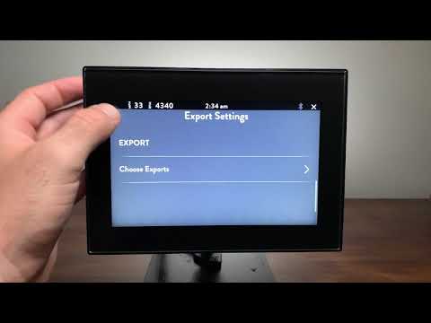
- Insert the flash drive into a USB port on display.
- Unlock restricted settings in Settings > General > Restricted Settings.
- Go to Settings > General > Settings Import/Export > Export Settings.
- Custom export options (or skip to next step):
- Tap Choose Exports.
- Select which types of settings should/shouldn’t be exported (if they are present in the file).
- Tap EXPORT
- The connected flash drive now has the preset settings loaded.
Restore Factory Settings
Restoring factory settings destroys all custom settings such as rider profiles and settings and returns your device to factory defaults. To restore factory settings, go to Settings > General and tap Restore Factory Settings.
Going back to the last imported jinst/jset settings (Restore Factory Settings) vs completely wiping all NV data back to the pv1's defaults (Factory Reset)
Factory Reset
A factory reset should be performed with caution, as it destroys all settings stored in the unit. To perform a factory reset go to Settings > General and tap Factory Reset.
Debug
Debug page show details useful when troubleshooting systems issues.
Restricted Settings
Some functions are limited through the user interface. Contact your dealer or manufacturing for appropriate password.
Display Settings
You can customize the display settings to make the screen easier to see with the following settings below.
Adjusting the Backlight
To adjust the device screen brightness, go to Settings > Display and use the arrows to adjust the brightness from 0-100.
GPS / Ambient Auto-Brightness
Note: This menu item may only be editable to Factory and Dealer users
On supported models, use GPS or Ambient Auto-Brightness to automatically adapt the brightness of the display to match the light in your environment. To access this menu, go to Settings > Display > Brightness and tap on the settings to enable.
Note: GPS brightness uses GPS time of day and GPS location to determine sunrise/sunset and dims the display accordingly.
Ambient Auto-brightness uses an external light sensor (sold separately) to determine brightness level
Theme
The system has two preloaded themes Dark and Light to adjust the display, after selecting one, the system reboots.
Theme Color
The primary theme color of the system can be selected using a color picker.
Theme Secondary Color
The secondary theme color of the system can be selected using a color picker.
Note: Note: This current menu item may only be editable to Factory and Dealer users
Stereo Page
This option enables the view of the Stereo page.
Map Page
This option enables the view of the Map page.
Use Wake
This option enables surf/wake functions
Use Marine
This option enables Navionics Maps
Use Full-Page Switches
This option enables the view of the Full-Page Switches page.
Horizontal Encoder Orientation
The encoder (also know as Smart Knob or VDC) is vertical by default. Selecting this lets user mount horizontally.

Customizing the Startup Screen
You can personalize the startup, splash screen on your device.
- Insert a flash drive that contains the images you want to use.
- Each image should be sequentially number *.png file starting with “0.png” (e.g., 0.png, 1.png, 2.png, 3.png, …)
- Select Settings > Display > Load Custom Splash Animation
- Tap Continue on the prompt to implement your customer splash screen animation on the device.
- Tapping on “Reset Animation” resets the animation back to the default loading animation.
To view the splash screen with the new image sequence, restart the device.
Images must be .png and the sized exactly as in the table.
Kit
Screen Resolution
800 x 480 Pixels
1280 x 768 Pixels
1280 x 480 Pixels
Bluetooth Settings
This device is Bluetooth compatible. To connect Bluetooth, follow these steps:
Bluetooth on the settings display, the following may appear:
Device List: Tap to connect to a different device source, disconnect, or delete a device.
Discover Device: Tap to add a new device.
Pairing a Bluetooth Accessory
To pair a Bluetooth accessory, tap Settings > Bluetooth > Discover Device, before touching confirm to scan for new devices, ensure your device has Bluetooth enabled and set to scan for devices. Select your device from the list of available devices shown on the list. A pairing request screen appears on both the device and your device. Tap the prompt to approve the paring.
<Include step by step photos> + <iPhone and Android>
After you pair your accessory, you can use it with your device. To pair multiple Bluetooth accessories, repeat the steps in this section. Your devices stay paired until you unpair them.
Unpairing a Bluetooth Accessory
To unpair, a Bluetooth accessory, tap Settings > Bluetooth > Device List, find the device you want to unpair and tap < Trash Bin Icon > to unpair the device.
When you Unpair a Bluetooth on your device, that accessory removed from the list of available Bluetooth devices, to add the Bluetooth accessory to your device again, place it back in discovery mode, and repeat the steps above to pair it again.
Map Settings
Satellite Status
The Satellite Status page gathers data on prevailing satellites and shows the proximity of each. This is useful for troubleshooting speed and determining ideal mounting locations for GPS pucs. Multiple satellites are required to have GPS lock. Speed, maps, and cruise control will not be functional until GPS is locked It also displays the following information:
- Longitude
- Latitude
- Number of Satellites
- Strength
Show Tracks
Toggling between on and off changes the visibility of tracks on the map.
Show Waypoints
Toggling between on and off changes the visibility of waypoints on the map.
Map Color
The system has three preloaded colors, Blue, White, and Black to adjust the map color.
Importing or Exporting Tracks and Waypoints
You can bring your Tracks and Waypoints from one device to another, by manually exporting them and then importing them on another device. Files must be in the .gpx format.
Importing Tracks and Waypoints
- Load a *.gpx file onto a flash drive.
- Insert a flash drive into a USB port on display.
- Go to Settings > Map > Import Tracks/Waypoints
- Select and import the tracks or waypoints loaded on the flash drive.
Exporting Tracks and Waypoints
- Insert a flash drive into a USB port on display.
- Go to Settings > Map > Export Tracks/Waypoints
- If you select Tracks, you individually select which tracks to import.
- Waypoints automatically export all waypoints on the device.
Power Distribution Module Settings
Note: This menu item may only be editable to Factory and Dealer users
If PDM is still not showing, you may need to enable it by going to ‘Restricted Settings.’
From PDM on the settings display, the following may appear:
Number of PDM’s: Tap to configure the number of PDM’s, up to four PDM’s can be set but only 12 icons can show on screen
Configuring PDMs
To configure an output on the device to control an accessory, do the following on your device. Go to Settings > PDM > Configure PDM (Depending on the configurations choose #1 or #2) and tap on an Output to configure and the following may appear:
After you save your configuration, you can use it with your device. To configure multiple accessories, repeat the steps in this section. To learn how to interact with each configuration by going to the ‘Engine Data’ page section.
Fuse
Each output is software and hardware monitored for overcurrent, short circuit, and open circuit. In the event of failure, the corresponding button will show a warning state and a Diagnostic Trouble Code popup will occur. Fuses are resettable and may require a restart of the system.
Output Types
You can customize the behavior of each output by selecting an output type from the PDM menu.
An Always ON output works as a fused circuit for devices that need circuit protection and constant power. No indicator will show on the screen but the output will still have circuit protection notifications.
A Latched output will maintain it’s state after being activated. This is a standard toggle function.
Momentary outputs only energize while the touch point is being activated.
Low/Mid/High is a 12V output that steps between 33%, 66% 100%, PWM, Ideal for heaters and fans.
Switch Control tie directly to the corresponding digital input. Whenever the input is switched to battery ground or 12V, the output will turn on. This allows the output to be controlled from a rocker or toggle switch. You can choose whether or not to have an on screen indicator for the output. In Switch Control mode, the on screen button only serves as an indicator and does not operate as a touch zone. Switch control can only be enabled on outputs 3-12.
Marine Specific Outputs
The PDM output types include some marine specific functions.
Bilge is a configurable latching output. The corresponding input serves as an auto-bilge or high water warning. Bilge output can only be enabled on outputs 3-12.
Blower output type turns on an output automatically for 3 minutes after first booting up and the user can manually turn the output on and off using the on screen indicator
Audio Settings
From Audio on the settings display, the following may appear:
Tuner Region
The tuner allows you to adjust your signals to be received by regions. The regions that can be selected are North America, Europe, and Australia.
Amplifier Outputs
Note: This menu item may only be editable to Factory and Dealer users
700 and 1200 display contain 1 amplifier output. 1100 has three amplifier outputs. Amplifier outputs are a 12V output signal that should be wired to the remote or “turn on” input on the audio amplifier. This allows the display system to power off amplifier when not in use.
Name Zones
Note: This menu item may only be editable to Factory and Dealer users
If you have wired your vessel’s speakers into zones, you can rename those zones to describe the zone. To change the name, tap on the zone to rename and enter the new name.
Engine (Vessel) Settings
Note: This menu item may only be editable to Factory and Dealer users
Presets
This menu entry will select the data type for the main engine page cluster values. By default, this will be J1939. Some marine engines transmit engine information in NMEA2000. Refer to engine manual for engine data type.
CAN Bit Rates
These menu entries are not configurable and list what baud rate the CAN port is transmitting. Standard NMEA2000 an
CAN Termination
This toggles internal 120 ohm termination.
CAN 2.0 networks require a 120ohm terminator on either physical end of the network. When both properly installed, the impedance between CAN H and CAN L will be measured at 60 ohms. The CAN bus may work as expected at 120 ohms. If no termination is present or over terminated (impedance < 60ohm) the CAN bus will not work properly.
Fuel Sender Location
There are two options for connecting a fuel sensors, at the display on Analog Input 1, or at the PDM on Analog Input 4. Select the location from the menu.
Fuel Sender Calibration
By default, a fuel sender is set as 240-33 ohm. This step through allows for a custom fuel calibration for different senders or curved tanks. The fuel tank calibration process is the step-by-step fuel tank refueling from “Empty” up to “Full,” with a predefined amount of fuel for each step, and fixing the mapping between the level code and volume in the calibration table. Tap to begin the process and follow the steps shown on the page.
Configure Gauges
This option allows you to display key features on the vessel/vehicle on the bottom bar of the device. To configure the displays, tap on Footer option, and tap on the data to display on the bar.
Camera Page
This option enables the view of Camera Page on the Engine Monitoring Page. Cameras must be NTSC.
Modifying Cameras
To modify the view of the camera tap on Camera 1 or 2 and select the appropriate settings from the options as follows: Mirrored, Not Mirrored,
Cruise Controls
This option enables the view of ZeroOff Cruise Control on the Wake Page.
Use MEFI Cruise [BETA]
This function is not currently supported
Engine Diagnostics
Engine Diagnostics displays a list of engine fault codes and descriptions. Tapping on “Get Stored Engine Faults” sends a request to the Engine ECM on the bus to report any errors found.
Wake Settings
Note:This menu item may only be editable to Factory and Dealer users
Number of Ballast Tanks
Edit number of ballast tanks from 0-3. This will configure PDM outputs as reversible pump control.
Ballast Empty / Fill Times
This page controls the length of time it takes to fill and drain the ballasts. Tap on the setting to adjust, and a keyboard appears to enter in a time.
Number of Tabs
Edit the number of tabs from 0-3. This configure PDM outputs to control electric trim tabs
Actuator
To properly drive tab actuators, the exact model must be selected from the menu.
Auto Retract
Auto Retract is the automatic active control of the tabs by the system. You can configure the speeds the tabs retract when specific speeds have reached. Auto Retract is turned ON/OFF in this menu.